Page 1 of 1
Loads through wing struts
Posted: Thu Mar 13, 2014 12:17 pm
by Exosock
Hello again!
As part of a group university project, my team is looking at the CH 701 main gear in HyperWorks. This was made unexpectedly more complicated by the inclusion of wing struts (
http://www.zenithair.com/stolch701/data/701-views.pdf), which just happen to be attached to the gear mounting brackets. Turns out, we don't know what loads are actually going through the struts, so we can't get an accurate figure on what the brackets have to put up with.
Could anyone point to any estimates for the loading through the spars?
Re: Loads through wing struts
Posted: Thu Mar 13, 2014 10:47 pm
by Basil
Are you talking about the loads through the struts during landing?
Re: Loads through wing struts
Posted: Fri Mar 14, 2014 10:05 pm
by Exosock
Sorry, I really should have specified that earlier. It is indeed for landing. I'm pulling together some moment calculations to see what loads are going through the wing. According to Pazmany's weight estimate model, the wing should have an empty weight of around 58kg, with two 38l (10 US gallon) tanks in the root sections.
Unfortunately, I have no load data on the wing spar or struts, though I do have a load rating of +6 to -3G. I do know that the struts extend from the very bottom of the fuselage to the midpoint on each wing panel, and the respective angle of said strut from the horizontal.
Re: Loads through wing struts
Posted: Sat Mar 15, 2014 7:45 am
by Ian Melville
is that 58kg for both wings?
Re: Loads through wing struts
Posted: Sat Mar 15, 2014 11:53 am
by Exosock
58.1kg for both wing panels, yes. I do keep forgetting to add these details...
Re: Loads through wing struts
Posted: Sat Mar 15, 2014 7:37 pm
by Ian Melville
I am no expert

and my advice is worth what you paid for it.
Assume no lift, worst case, -3G (downwards)
I would assume the constant cord wing has it's weight evenly spread along the length. You will also need to know the position of the tank C of G, and it's weight full.
From that you should be able to create the force diagram for the wing and tank acting on the strut end in compression.
Que expert advice

Re: Loads through wing struts
Posted: Sun Mar 16, 2014 7:21 am
by Brian Hope
Hi Ian, I'm definitely have a minimal knowledge about these things too but if the lower ends of the struts are attached to the undercarriage bracket then are not both positive and negative situations subjecting load into them, either in tension with positive G and compression with negative?
And is the weight of the wing panel, or any fuel weight within it, relevant? The wing carries the weight of the aircraft, which if the design is stressed to say +6 -3 amounts to a quite considerable load. I'd have thought the stresses going through the lower strut/undercarriage fitttings were dependant on how much of that ultimate load the strut carries, the remainder being carried by the wing root/fuselage attachment. The amount of work the wing does reduces as you move out towards the tip, so does the wing strut only do, to pluck a figure from the air, 30% of the work and the root/fuselage fitting 70%? I haven't a clue but I'd have thought whatever that percentage was, multiplied by the positive and negative load factors, plus a safety factor, was what the lower u/c fitting needed to be able to handle – notwithstanding any forces the undercarriage itself might or might not put into the fitting, particularly in the landing situation.
Re: Loads through wing struts
Posted: Sun Mar 16, 2014 7:56 am
by Ian Melville
Hi Brian, Yes positive loads will also apply at times but the OP is working on the undercarriage, which I assume means he is interested in the landing or take-off phase, fully stalled would be the worst case? During take off there will be a mix of lift and ground loads but I would have thought that impact (nice choice of word

)on the gear mount would be less that a full stall onto the deck from the prescribed height.
The wing/fuselage joint is considered a pivot on a strutted aircraft. Though a hybrid is possible, I don't think the Zenith CH701 is one.
You are quite right that as a whole the stressing should be considered for all eventualities. The hard sums need to be done for all the worst cases and areas of doubt but there will be many incidences where it will pass test A if it passes the tougher test B. I did forget the safety factor.
Re: Loads through wing struts
Posted: Sun Mar 16, 2014 8:18 am
by ColinC
Hi,
Is this the bracket?
http://api.ning.com/files/i0u8roW8Lp3Pm ... talled.jpg
Have you emailed the designer? As someone who publishes a lot of material he may be willing to provide some data for your project.
Regards,
Colin
Re: Loads through wing struts
Posted: Sun Mar 16, 2014 8:39 am
by Ian Melville
Is there not a danger that we will do too much of Matthews homework for him
Re: Loads through wing struts
Posted: Sun Mar 16, 2014 10:40 am
by Bill McCarthy
It may not be relevant, but as I see it, the wing spars and struts of any light aircraft see far more stress excursions (in some instances) on the ground than in the air. Quite often you will see an aircraft taxi on rough ground and the wings tips will violently snatch up and down as it runs over ruts across it's path. It can't be doing any good.
Re: Loads through wing struts
Posted: Sun Mar 16, 2014 6:47 pm
by Ian Melville
Very true Bill, but the OP is tasked with looking at the main gear.
I posted this morning that I agreed with Brian that I had forgotten about the safety factor. After waking up properly, remembered that it is not relevant to the OPs question. Safety factor, IIRC, is only applied when dimensioning the part.
Re: Loads through wing struts
Posted: Tue Mar 18, 2014 11:51 pm
by Exosock
Homework? For shame. We do not use that term anymore. Well, maybe apart from that one time...
Apologies for going dark, we have found our energies consumed by a seperate UAV project from dawn to dusk every day for the last two weeks. In between times, we've produced some basic figures and successfully created a mesh. Simulation results are pending.
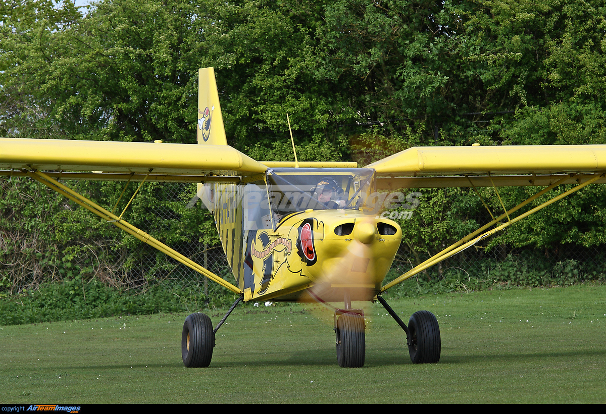
I contacted ZenAir a week or two ago but haven't received a reply. However, I had a bit of a brain fart and neglected to check the source of our technical drawings, and I discovered only yesterday that my team mates had obtained them from a non-Zenair site. I imagine my message might have therefore appeared somewhat confusing. Further, the main gear we are studying is the system used by the original CH 701, which has long since been abandoned (see image)

Note how the gear drops away at a shallow angle, pushing the wheels further outwards than downwards compared to the later configuration.