To try to get the best signal ( if VHF radios are still in use when I finish my project..my hearing might not be so good then, either?), I'm making up a dipole antenna, to fit inside the fuselage of my "Boredom Fighter", while access is still easy. The antenna elements form a wide "V" shape and each arm has to be 23-5/8" long.
From what I've read, the aerial should ideally be mounted vertically ( of course ), although a bit of leeway is available. The example shown has the "pointy" end of the "V" facing the back end of the aircraft, but this would not work for me; it would have to be the opposite way round to allow the 10 inches or so of the upper end to stick up above the turtle deck and slope backwards a little, rather than forwards, to "sit" better in the airflow.
I'm assuming this would have not the slightest effect on the quality of the signal, but it would be near impossible ( that is, I wouldn't have time ) to change the aerial orientation after covering the aircraft.
Any advice would be appreciated.
Ian
Dipole antenna - positioning in fuselage
Moderators: John Dean, Moderator
Re: Dipole antenna - positioning in fuselage
Hi Ian,
I am not really an antenna expert but take a look here:
http://www.aircraft-spruce.com/catalog/ ... ystems.php
I would have thought a VHF comm antenna (not for VOR use) woudn't be a "V" shape, but vertical (or near vertical).
Tony Nowak
I am not really an antenna expert but take a look here:
http://www.aircraft-spruce.com/catalog/ ... ystems.php
I would have thought a VHF comm antenna (not for VOR use) woudn't be a "V" shape, but vertical (or near vertical).
Tony Nowak
Tony Nowak
008249
008249
Re: Dipole antenna - positioning in fuselage
Thanks Tony - I remember seeing these aerials advertised somewhere, but hadn't spotted the "FAQ" list.
Very useful and I will assume from the above and other comments I have since read that the exact alignment isn't critical enough to worry about, in my particular application!
As mentioned, a short length of the upper arm will have to exit the top surface of the "turtle deck" and since it is bare steel exposed to the weather and rain, it will need some corrosion protection. I think "AC43" warns against painting the antenna unless suitable paint is used, but I can't find what this is. I will try using my usual 2 pack etch primer, which is claimed to be water proof to some extent, but it could do with another coat of something more substantial. I'm still looking for the best ( and cheapest ) solution to this.
Ian
-
Steve Brown
- Posts: 257
- Joined: Wed Jan 02, 2008 11:00 am
Re: Dipole antenna - positioning in fuselage
Hi Ian - if it helps, you could do worse than something similar to our setup.
Remember both elements of the dipole don't have to be vertical.
We have installed a home made comms antenna in our winglet (which is only approx 24" high) at the end of the wing. This setup was exactly as recommended by Rutan - ie effective, simple, cheap and zero maintenance.
The centre wire of the co-ax is soldered to a 20.5" long x 1/2" wide copper foil tape that runs vertically up the leading edge of the winglet - probably inclined about 15 deg backwards from the vertical. The vertical section does all the radiating and receiving.
The shield of the co-ax is soldered to a 20.5" long x 1/2" wide copper foil tape that runs horizontally and span-wise along the upper surface of the wing, just aft of and parallel to the leading edge.
The tapes are thus at right angles to each other.
I rounded off all 4 corners of the vertical tape to minimize sharp edges/points that could disrupt the power radiation pattern and similarly on the horizontal one for good measure.
Spacing between the ends of the tapes was about 1/4" and you need to install 3 torroid ferrite rings over the end of the co-ax spaced apart by the thickness of the rings to suppress stray currents.
eg http://uk.rs-online.com/web/p/product/1 ... wwodY3EA2Q
After a continuity check, the tapes were covered with a single ply of BID tape and the soldered connection potted in epoxy/flox below the wing skin and normal finish /primer / UV barrier etc applied over them.
Both transmit and receive performance is simply outstanding. We have listened to aircraft transmitting in South Wales while crossing the Channel at Dover and we never have any problem speaking to ATC/FIS etc.
Regards
Steve
Re: Dipole antenna - positioning in fuselage
Many thanks Steve and this gives me even more confidence to go ahead.
The design I have been trying to follow uses a "Pawsey Stub" rather than the torroids. It is all way beyond my limited knowledge of radio, so I'm grateful for all suggestions. The copper tape would certainly be much easier to install & I'll investigate that.
Regards.
Ian.
The design I have been trying to follow uses a "Pawsey Stub" rather than the torroids. It is all way beyond my limited knowledge of radio, so I'm grateful for all suggestions. The copper tape would certainly be much easier to install & I'll investigate that.
Regards.
Ian.
-
Steve Brown
- Posts: 257
- Joined: Wed Jan 02, 2008 11:00 am
Re: Dipole antenna - positioning in fuselage
Yes - I read up about the balun and short lengths of co-ax etc but opted for the torroids on grounds of simplicity and limited space.
I also built a Mode S transponder dipole using a bit of etched printed circuit board and that works amazingly too, again using torroids. Never had any issue with ATC 'seeing' me.
Best of luck
Steve
I also built a Mode S transponder dipole using a bit of etched printed circuit board and that works amazingly too, again using torroids. Never had any issue with ATC 'seeing' me.
Best of luck
Steve
-
Ian Melville
- Posts: 1001
- Joined: Mon Feb 11, 2008 7:21 pm
Re: Dipole antenna - positioning in fuselage
Though no expert I did study antenna design when I did my apprenticeship many moons ago.
I suspect few aircraft have the best config for an antenna. There are always going to be compromises that will reduce the performance. Most of the time it just results in a reduced range, but not enough to make any difference. Length is important and each installation should be fine tuned. The transmit section of the radio can overheat if you get it wrong.
Ground stations we use are vertically polarised and the receiver antenna should be the same. i.e the active element should be vertical. The ground plane (as described by Steve above) can take many forms. Flat plates, radiating tape cone and sticky foil have all been used. They are not dipoles, but a 1/4 wave whips.
A dipole should have the ground element attached to the cable screen and pointed straight down to give a balanced range all around. Forming it into a wide V as described in the OP will, I think, bias the signal in one direction. I would guess towards the smallest angle. Raking back would improve the range to the rear. To be honest it will all get a bit theoretical and involve a lot of maths, which in the real world will fall flat on its face. Then it is down to testing, testing, testing.
Good quality cable and connectors are also important.
You can always replace you upper element with Stainless Steel wire. Are you sure it is not already stainless?
Ian Melville
032644
032644
Re: Dipole antenna - positioning in fuselage
Many thanks Ian. I'm accumulating a lot of useful information & grateful for all the advice.
I hoped to try the dipole rather than the 1/4 wave type, to improve radio performance in what is likely to be a noisy and draughty cockpit.
So far I've made the simple plastic base block and have temporarily mounted a pair of 23-5/8" long piano wire rods in place, at an angle of 130 degrees to each other, so I can attempt to fit this inside the rear fuselage. It fits best about 12" behind the seat, but with open end of the "V" pointing to the back rather than the front. When I am fairly sure it will fit and has a reasonable chance of working, I'll get hold of the RG-58 and few other bits I need.
I had intended using 1/8" brass rod for the 2 arms.
The web item I'm following shows the designer's example mounted near the tail of his "Weedhopper", with the open end of the "V" pointing to the front, but otherwise it is vertical. He actually used old wire coat hangers for his antenna elements and reports it works very well. This wire is soft and easy to form mounting/terminal loops for the co-ax, connected as you indicate. Looks like several more similar examples have been made by others, who report a good performance.
Thanks again & I'll report back on my success or otherwise!
Ian
-
Ian Melville
- Posts: 1001
- Joined: Mon Feb 11, 2008 7:21 pm
Re: Dipole antenna - positioning in fuselage
The thinner the rods, the narrower the bandwidth. Coat hanger will work perfect at one frequency (e.g. the centre of the airband) but performance will fall off towards the upper and lower ends. Tubes are best as they will be lighter. the currents flow in the skin of the metal, so the core is dead weight.
This is a plot of one I made with 15mm copper pipe. only the cable and connector didn't cone from screwfix Not much use in an aircraft though. I can hear traffic over 20 miles away on my hand-held. Ignore the green. Low is good
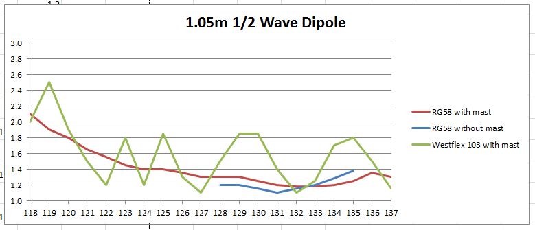
This is a plot of one I made with 15mm copper pipe. only the cable and connector didn't cone from screwfix
Ian Melville
032644
032644
Re: Dipole antenna - positioning in fuselage
Thanks again Ian.
I did wonder about using thin brass pipe to reduce weight but need something no larger than 3mm & the short length outside the fuselage may not be stiff enough. I have to watch the added weight; the Boredom Fighter CG nearly always ends up too far aft.
I assume I can't use tube for the lower "arm", inside the fuselage and rod the upper "arm", half of which will be outside in the airflow.
Ian
-
Ian Melville
- Posts: 1001
- Joined: Mon Feb 11, 2008 7:21 pm
Re: Dipole antenna - positioning in fuselage
Ian, there will be little or no benefit. It also may be a pain to get tuned. Stick with 2mm ish stainless steel rods both sides( brass is too brittle). It Will be more than stiff enough, unless you put one of those Micky Mouse aerial toppers on
If you don't know where to get the rod, try here http://www.metalmaniauk.com/product/sta ... 000mm-780/ Order two 1metre lengths.
Just noticed that you have each element at 23 5/8th" this is a little long, but would be a good length to start trimming from. 21.5 to 22" would be closer to the centre of the airband range. If you have a VSWR meter then start long and nibble equally at each end until you get the centre dip at the frequency you want.
Ian Melville
032644
032644
Re: Dipole antenna - positioning in fuselage
That looks like a good plan.
Many thanks for all your advice.
I'll try to make some progress and get the job done, now.
Ian
Many thanks for all your advice.
I'll try to make some progress and get the job done, now.
Ian
Re: Dipole antenna - positioning in fuselage
Excuse the thread drift but can anyone recommend a source of copper strip suitable for using as a bus bar in connecting circuit breakers?
Mike Mold (007106)
Jodel D117A G-BFEH, Watchford Farm, Devon
Jodel D117A G-BFEH, Watchford Farm, Devon
-
Julian Bone
- Posts: 9
- Joined: Thu Jul 03, 2008 7:19 pm
Re: Dipole antenna - positioning in fuselage
A dipole is normally straight not a Y shape.
Calculate length for speed of light, less 5 percent for copper.
Dipole normally total length of half a wavelength.
To increase bandwidth use thick legs or several wires which can be thin to save weight.
Spread wires approx 2 inches apart and bring together at the end of the elements.
Ideally a birdcage design but will work satisfactorily in one plane, ie glue wires to a flat surface ideally inside fin for vertical polarisation.
Ideally check resonant frequency with an antenna analyser, MFJ make some that are very easy to use find a friendly Radio Amateur to help trim to length/estimate error once glued into
airframe, any structure seems to slow the wave needing it to be cut a bit shorter.
Broad elements also necessitate some length reduction.
Three wires per leg makes sense in that the frquency can choose which leg length it prefers.
/--------\ /--------\
\--------/ \--------/
Thats the best I can do with text!
One leg connected to inner of coax one leg connected to outer of coax.
Also it helps reduce interference pickup if several ferrite rings are placed on the coax near the aerial.
Ferrite rings on the coax will not reduce the wanted signal no matter how many are fitted.
Please do not respond to this with minor technical quibbles, I am aware of them all and they are not helpful.
021184
Re: Dipole antenna - positioning in fuselage
Many thanks Julian and more serious food for thought.
My options are still open and I'm grateful for your advice.
Ian
My options are still open and I'm grateful for your advice.
Ian